ENGINEERING SIMULATION CAN REDUCE CAPEX AND OPEX FOR FRACTURED SHALE WELLS IN THE PERMIAN BASIN
The oil and gas industry experienced extremely challenging market conditions during the downturn and recent pandemic. Now, with the price of crude nearly double what it was a year ago, this should be a period of significant growth for the industry. With U.S. shale often perceived as the sector most able to quickly adapt to changing market conditions, much focus and expectation has been placed on established plays, such as the Permian basin, to increase production and fill the gap between demand and supply.
However, pressure from the environmental lobby to reduce the dependence on hydrocarbons, plus supply chain blockages creating longer lead times, the need to generate guaranteed maximum investor returns, a focus on minimizing expenditure, and a rapid increase in demand for raw materials, such as frac sand, continue to create challenges for the Permian basin and elsewhere.
With the current trend to drill ever-longer lateral shale wells, the demands placed on frac iron infrastructure—the networks of surface pumps, pipes and manifolds—increase. In shale wells, the volume of solid content in the frac fluid can be very high, coupled with high flowrates resulting in a fast and highly aggressive flow regime, increasing the risks of pipe wall damage through erosion. Many of these pipes often have a short radius or 90° bends, which increases the turbulence of the fluids and solids within them, creating the potential for significant erosion damage.
Erosion, due to solid particle impacts, can be a major problem. Being able to reliably predict erosive wear can allow operators to extend the life of their fracing equipment and ensure that no damage is done to the permanent well hardware, such as the wellhead, casing, and tubing hangers.
Traditionally, estimations have been achieved with varying degrees of success, through the lengthy and expensive process of experience in the field, regular experimentation, and calculations using established equation methods before the frac iron is installed, and a review of how and why infrastructure was damaged, once an event has occurred.
If a fluid flow contains solid particles, then erosion of the walls bounding that flow may occur. This can cause a wide range of problems. In many cases, equipment development costs increase, and the equipment still requires regular repair and replacement. Erosion also can have significant implications for safety and the environment, if the failure of a component or pipeline leads to a loss of containment of a hydrocarbon.
However, the recent growth in digital technology adoption across the energy industry is enabling operators to better understand erosion rates and predict outcomes with greater sophistication, and with a much higher degree of certainty than ever before. Deploying multiple simulations enables processes to be optimized, pressure losses reduced, and erosion minimized from the outset.
Such an improved understanding of the flow and resulting erosion rates can assist in extending the performance of the frac iron. This can enable increased production optimization and efficiencies, reduced safety and environmental risks (such as containment losses and the identification and implementation of CO2 reducing processes), and lower operational expenditure (OPEX) and capital expenditure (CAPEX). This is done through more efficient use of raw materials such as sand, longer-lasting frac hardware or even re-use of infrastructure.
At the heart of this improved understanding of erosion is the discipline of computational fluid dynamics (CFD). This is a digital engineering simulation technique that can be used to explore almost any fluid flow problem. CFD, previously seen as a specialist scientific endeavor, has been used in a wide range of industries for many years. Its sophistication and capabilities have evolved along with computing power, to deliver ever-greater accuracy, reduced solution times, and wider adoption today.
The ability to run multiple simulations to consider every scenario means CFD can be an accurate, reliable, and highly effective way to predict erosion caused by sand-laden flows. The location and extent of erosion damage can be determined, and the primary fluid dynamics that underpin the damage mechanism can be understood and therefore mitigated. This enables operators to ensure that the lifespan of hardware is maximized.
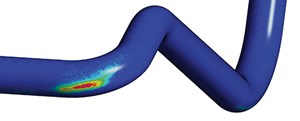
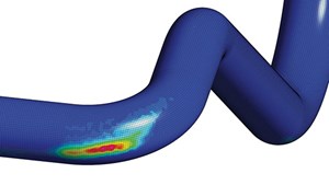
Erosion analysis using CFD (Fig. 1) can be applied to production pipework and equipment, but also to well control equipment for incident response planning (such as erosion during a well kill, and diverter system integrity checks).
Ensuring that the simulations are accurate is paramount, but it can be challenging, particularly for high sand-loading flows, and the erosion rate during any fracing operation is not a constant. The rate of material loss changes as the wall is eroded away. Modern CFD tools can now account for this, leading to more reliable
predictions.
Some of the well control fluids used, such as heavy kill mud, can be almost 50% solid material. In some well control scenarios, very high flowrates of these heavy muds are pumped into the well, potentially damaging the critical well control components. It is, therefore, important to understand the risk to every part of the flow path.
Changes are easier and less costly to implement in a digital environment than in the real world. Using multiple simulations to identify the need for subtle fluid dynamics changes in local flow speed or turbulence levels, for example, can significantly reduce erosion where materials, such as quartz sand, are present in the flow stream.
In the highly cost-conscious shale industry, with an acute focus on the bottom line, a short-term reluctance to invest in CFD predictive modeling can prove to be an extremely short-sighted and significantly more expensive decision. This is true when compared to the cost of replacing damaged frac iron or repairing damage to the operator’s wellhead or other completion hardware.
INCREASING PERFORMANCE CERTAINTY
It must be acknowledged that several analytical calculation methods already exist in the industry that do not involve CFD. These often can be a good starting point for initial asset assessment. These empirical erosion correlations are used primarily for exploring simple geometries, such as pipe bends, contractions, expansions, cushion tees, and flat plates.
However, these empirical models are global in scope and are capable of yielding only an average or maximum erosion rate, Fig. 2. In reality, complex geometries typically contain very complex flow patterns that can cause the erratic behavior of entrained sand. In these conditions, empirical models often can break down, and a more advanced solution is required.
CFD is an ideal tool for capturing both complex geometry and complex flow fields, including flow path optimization, the effects of turbulence, particle size distribution, time-varying conditions such as flowrate, and an unlimited range of geometries. For these reasons, developing a CFD model to enable multiple simulations, in effect virtual experiments, should be considered at the very beginning or the concept stage of a project, alongside the identification of objectives. It can provide quick answers to the various “what if” project postulations and offer novel solutions that may not have been considered otherwise.
PREDICTING EROSION WITH CFD
Several factors need to be considered in generating an accurate CFD model. Erosion does not occur in a uniform, constant manner across the entire length of the frac iron. The inconsistent erosion rate of a pipeline’s inner wall affects the local flow path, which is a critical issue to consider in achieving an accurate assessment of overall erosion. This is of great importance when considering the current development trend for longer laterals in the Permian basin and other shale plays. Similarly, calculating erosion rates using pristine or brand new frac iron geometry also risks a gross miscalculation of the potential for erosion.
Using CFD enables a detailed local assessment of the effects of the deforming wall on erosion, including changes in particle trajectory, impact velocity, and angle. These data can be compared with pre-defined erosion correlation calculations to accurately assess the distribution of localized erosion damage, not just the overall erosion rate.
Aside from erosion prediction, CFD is also used in retrospective applications, where a forensic study is required to identify the reasons for an incident occurring or material damage. Because of its ability to explore situations from every angle, CFD often can provide answers to questions that had not been considered previously. Ensuring that CFD simulations are validated robustly increases customer confidence in the accuracy of the outputs and a greater degree of predictability in performance outcomes.
Wild Well Control has a long record of performing erosion analyses as part of its portfolio of computer-aided engineering, CFD, and finite element analysis (FEA) services from its specialized advanced engineering team. The company uses the latest CFD techniques and has validated its analysis methodology against physical tests.
CASE STUDY: DEPLOYING CFD IN EFFECTIVE EROSION ASSESSMENT
A U.S multi-stage frac equipment manufacturer was commissioned by Wild Well Control to carry out an erosion assessment, simulating the frac conditions to better understand the fluid dynamics and predict likely erosion damage to the equipment in advance of the frac job.
The primary objective of the project was to carry out the flow analysis of a frac manifold, using CFD to estimate erosion anticipated during the entire frac job.
Flow conditions. The process was carried out in multiple stages. The frac fluid utilized was water-based, flowing at a rate of 110 bpm, using 500,000 lbs of sand per stage; each stage was 1.5-2.0 hrs long. For conservative erosion estimates, a short-time frac stage was simulated, resulting in a more aggressive sand rate. The sand size was based on frac sand 40/70, with an average sand size of approximately 300 microns. Standard material properties for water and sand were utilized.
Approach. The erosion study was performed, using the CFD software Simcenter Star CCM+. An established erosion equation model was utilized within the CFD simulations and used to calculate erosion rates. The CFD software predicted particle velocity and impact angle as an input into the established erosion model.
Dynamic wall movement, due to erosion (physical loss of wall material), was accounted for during all stages. A customized code was developed to work in tandem with the CFD simulations to account for the transient wall movement, due to erosion during all frac stages. The erosion predictions were also benchmarked using multiple CFD codes.
THE RESULT
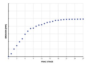
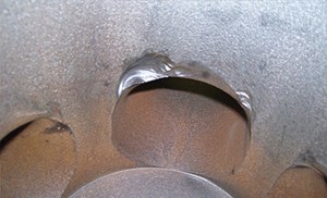
Cumulative erosion was identified on the wall of the frac manifold, and the erosion distance was measured after all frac stages, Fig. 3. Erosion was observed to rise rapidly and was predicted to level off from that point. Comparison of physical damage with erosion prediction showed good correlation. A key conclusion from this study was that without properly accounting for the wall movement, the erosion damage would have been grossly overpredicted.
Benefits of applying CFD for a range of applications. Alongside erosion analysis, Wild Well Control offers a range of simulation solutions incorporating CFD–including digital twinning, radiant heat analysis, fire and explosion analysis, and atmospheric dispersion analysis to support emergency response plans and emergency avoidance. The company’s experience base includes the Permian Basin as well as other U.S. shale plays and the onshore and offshore oil and gas industry globally.
Radiant heat analysis uses calculations and simulations to determine the magnitude of radiant heat energy generated by a fire. Results of this analysis can be used to determine the level of risk to personnel and equipment that are in proximity to a well fire or flare.
Explosion analysis offers studies of explosion severity, should a gas cloud ignite. It is aimed at quantifying risk to personnel, equipment, and infrastructure. Explosion analysis can include both high-level assessments, as well as detailed CFD analysis.
Atmospheric dispersion analysis uses calculations and/or simulations to predict the propagation of gas clouds from a blowout, leak or flare. Gaussian plume analysis or CFD is used to determine the concentration of flammable or toxic gases from the source, as gas is dispersed by wind and atmospheric turbulence. The results from atmospheric dispersion analysis can be used in the planning of safe zones and exclusion zones for well control operations, relief well operations, and the overall risk of exposing the surrounding areas to gas and cloud.
CONCLUSION
Digital engineering is increasingly changing the way that the energy industry operates, providing abilities to better understand and predict outcomes before a heavy financial investment is made or an incident occurs. Computational fluid dynamics (CFD) play an important role in the ongoing development of digitalization in the oil field. Through the delivery of greater clarity and predictability on project outcomes, it can provide significant CAPEX and OPEX reductions in the Permian basin, other shale plays, and conventional onshore and offshore assets.


 Upload RFQ



 Twitter
 Linkedin
 Facebook
 YouTube
 Sales@toplandoil.com
 +86 21-50890868
 Head Office: 8-1011,Lane 5600, Chuansha Road, Pudong, Shanghai, China